|
JWP4001 Swingaway Fitting Instructions
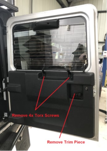
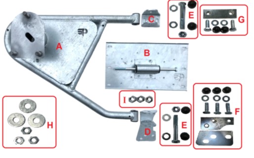 In the kit you will receive the parts as above. STEP 1 Next job is to remove the inner door card on the rear door,
the photo above shows the door card on 2002-2016 Defender models. On 1983-2002 door card the process is very similar, but
involves removing self taping screws from around the edge of the door card. 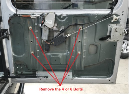 Next job is to remove the bolts holding the current wheel
carrier onto the door. On 1983-2002 doors the wheel carrier will be held on with
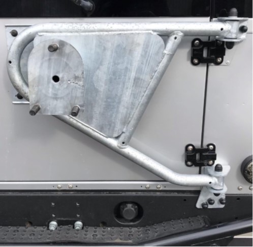
about 10-14 bolts  You can now bolt on the main backing plate (part B) reusing
the existing bolts. On 1983-2002 doors you may need to redrill or elongate some
of the holes as the holes in 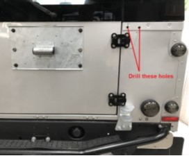 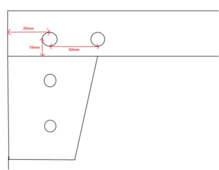 You will now need to drill the 2 holes in the tub capping to
mount the upper hinge (Part C) The holes will need to be 12mm in diameter. The LH hole is in
line with the pop rivet above. The top hinge (part C) can now be loosely bolted in place
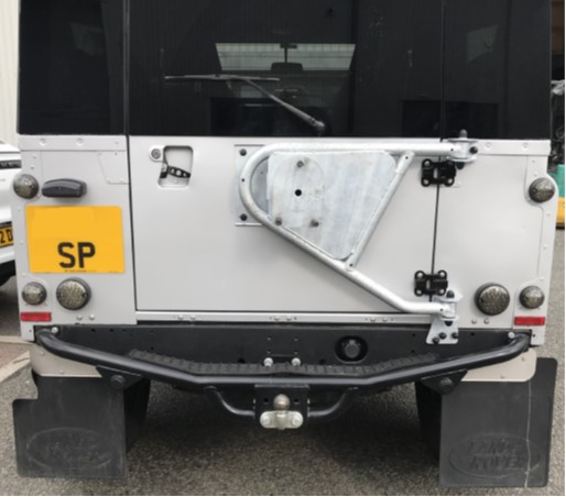
using the M10 bolts and captive plate (Part G). The Lower hinge (Part D) can now be fitted to the chassis
crossmember using the captive plate and M10 Bolts (Part F). At this stage please keep the hinges slightly loose. The main assembly (Part A) can now be bolted to the hinges
using the 2 M12 Bolts and nyloc Nuts (parts E). With the Main assembly now bolted to the hinges, you can now
tighten up the bolts attaching the hinges to body. 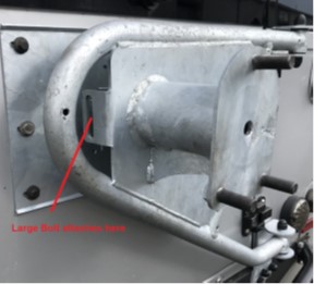 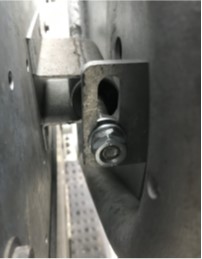
Please note the Large Bolt on part B is meant to be a snug
fit so will feel a bit stiff when sliding it through by hand. The bolt attaches through the slotted hole as above. It is
held into place using the 3x M12 Half Nuts (Part I)
. Then poke through the end of the bolt through the slotted
hole. You can then screw on one of the other M12 half nuts and tighten both.
Once you have refitted your door card, your swing away wheel
carrier is now fitted. You will also find in the fitting pack, plastic caps to fit
over the bolt heads on the hinges, both M12 and M10. If you are fitting a steel wheel you can bolt it straight
onto the wheel carrier. If you are fitting an alloy wheel or offset wheels, please
use the large thick washers and M16 half nuts on the 3 main studs |